Despite all of this, I’m still relatively new at Pure Data and the Max language. To those who chime in with corrections or clarifications in the comments, you are most appreciated! If you’re new to PD, make sure you check the comments section for clarifying info provided by generous souls.
In the last tutorial in this series, we achieved MIDI control of playback. It would be nice to have some of the features built into our MIDI controllers. So, today we’ll be implementing pitch bend and modulation…as those are two features common to most controllers. If you haven’t finished the other projects in this series yet, then I strongly suggest you do so before tackling today’s projects.
Let’s begin by adding pitch bend.
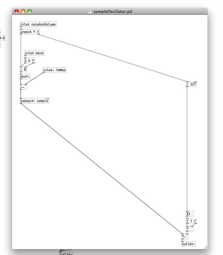
Remember to connect and configure your MIDI controller in PD before opening the patch. Open your patch from Part 5, open the [pd polytouchSynth] sub-patch, and then open your [sampleOscillator] abstraction patch. We’re going to start here and work our way out. To simplify things for ourselves, we’re going to work in MIDI note values. This will be far easier than trying to scale a frequency range based on the starting point. Why work with math that will have to involve logarithms if someone else has already done it for us? This means that we’ll want to affect the MIDI note value before it reaches the [mtof~] atom in our [sampleOscillator] abstraction patch.
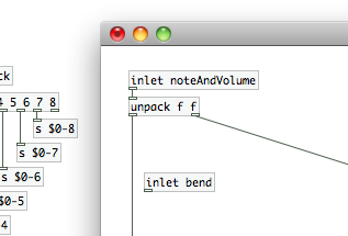
Let’s create a new inlet in [sampleOscillator] called “bend”. We’ll touch on this again shortly, but…as you add inlets to your patches and sub-patches the position of the “white rectangle” on the representative atom in your higher level patch will reflect the position of the [inlet] atom in the working patch. Placing [inlet bend], which we just created, to the right of [inlet noteAndVolume] means that the new right inlet on the [sampleOscillator] atom feeds [inlet bend].Remove the connection between [unpack f f] and [motf~], because we need our pitch bend value to change the MIDI note prior to creating the control frequency for [tabosc4~ sample]. Create a [t b f] atom and a [+ 0] atom. As in the past we’re going to connect these in a manner to ensure that a change in the pitch bend value always triggers the math atom to perform its calculation. Connect [inlet bend] to the inlet of our trigger atom [t b f]. The right outlet of [t b f] (the float) should be connected to the cold inlet of [+ 0], and the left outlet (the “bang”) should be connected to the hot inlet. We also need to connect the left outlet of [unpack f f] to the hot inlet of [+ 0]. Connect [+ 0] to [motf~], and our tasks for pitch bend implementation in this area are done. We add the zero to [+] as a fail safe, but we’ll be configuring [inlet bend] to always be receiving a value…even if it’s zero. So, the MIDI note from our controller will now always be passed to [mtof~], but will be shifted up or down according to incoming pitch bend values.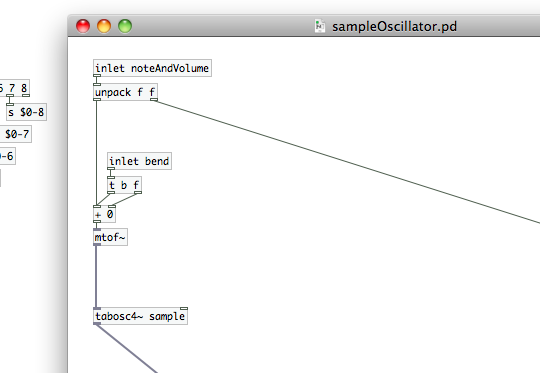
 Save the patch, and let’s close [sampleOscillator] for now…then move back up to our [pd polytouchSynth] sub-patch. [note: Sometimes you need to close and reopen the parent patch if you’ve made updates to an abstraction patch. If you ever do make changes to an abstraction that don’t seem to have taken affect across all instantiations, try that.] Take a look at the [sampleOscillator] atom. You should have a free inlet on each instance of it. Remember what I said about abstraction patches in the last article? Make a change, save it, and it will update all instantiations of that patch. Nice that we don’t have to go in and correct that in each patch, isn’t it? I’d like you to create eight [receive] atoms, all with the argument “$0-bend”. If you’d like to save yourself a little bit of time just create [r $0-bend], copy it, and paste it into the sub-patch seven times. Attach one to each of your [sampleOscillator] atoms. We’re going to use “$0-bend” as a global variable in our parent patch, and using the same receive variable at each instantiation of our oscillator patch will ensure that each voiced note gets pitched up or down the same amount.
We’re done in our [pd polytouchSynth] sub-patch now, so feel free to close it. I’d like you to create a new sub-patch in your parent file called “pitchBend”. PD has a built in object atom for receiving pitch bend information from a MIDI controller, [bendin]. Because its MIDI, the bend values output will span 0 to 127. Create [bendin], a number atom, and attach the number atom to the left outlet. The number atom is to give you a point of reference for your specific controller. The one I used when building this patch, an M-Audio Axiom 25, outputs a 64 in its nominal state (and 127 and 0 in its maximum upward and downward bends respectively). My upcoming math choices may seem a little strange, but this was the most accurate system I could devise with this particular combination of Axiom 25 and PD.
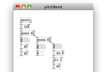
For some reason, the [bendin] atom on my system does not output MIDI values…despite the fact that that is what the Axiom 25 is displaying on its LCD when I adjust the pitch wheel. I had to create a [/ 128] atom and connect that to the left outlet of [bendin] to bring it back down into the MIDI note range. [Check out the comment from Matthew Thies at the bottom of the page for an excellent explanation why this is happening.] Confirm that your system behaves similarly before using [/ 128] in your own patch. Simply connect a number atom to [bendin] and adjust your pitch wheel. If it goes above 16,000 at the top of its range, you’ll need to use that [/ 128] atom. [The right outlet of [bendin] is simply channel number…which is not something we need in this patch.] We’re now going to use a pair of [moses] atoms, much as we did in the [pd sampleBuild] sub-patch we previously built. The arguments for these will be “63” and “65”. [moses 65] will be fed from the right outlet of [moses 63], which in turn will be fed by the outlet of [/ 128]. Create 3 number atoms and connect them to the remaining [moses] outlets. In my configuration the left outlet of [moses 63] outputs “0” to “63” when the pitch bend is moved down, the left outlet of [moses 65] only outputs “64”, and the right outlet outputs “65” to “127.9”. [The additional 0.9 is an effect of that frequency instead of MIDI note output from [bendin]…we’ll correct it shortly.]
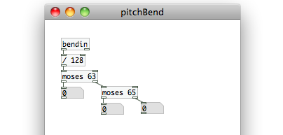 Let’s set these three outlets paths, from left to right, to produce the numbers: -1 to 0, 0, and 0 to 1. By doing this, we’ll have a simple way to scale the amount of pitch bend (up or down) based on a user defined range. Under the left outlet of [moses 63] create [- 64] (fed from the outlet of your number atom…you could also remove the number atoms and connect directly to the [moses] outlets), then create [/ 64] and connect that to [- 64]. This will give us a “-1” when the “bending” value is “0”, and a “-0.015625” when the value is “63”. Create a message atom with the number “0” and connect it to the number atom under the left outlet of [moses 65]. Whenever the pitch wheel returns to nominal, this path will output a “0”. Under the number atom in the right outlet path of [moses 65], create [- 63.9]. This will give us a maximum output of “64”. We now have the issue of potentially creating decimal values where we don’t want them. So, we will once again use [div 1] to restrict the path, prior to division, to whole integer values. [Goodbye “127.9 issues!] Create [/ 64] and connect those three in series, and this path will now output “0.015625” to 1.
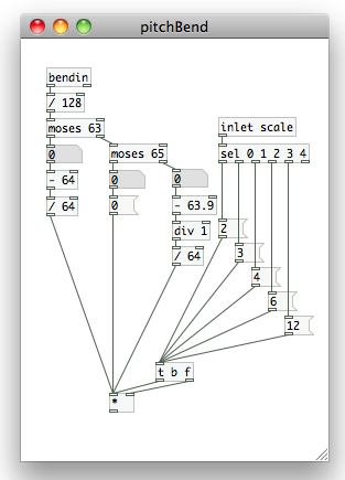
Let’s establish our range selections now. Create an inlet and label it “scale”. We’re going to use an object atom similar to [route] now. This one is called [select] (you can also use [sel] for short). While [route] actually sends data through a path based on incoming data, [select] simply outputs a “bang”. We want to create [sel 0 1 2 3 4], which we’ll feed from the parent patch shortly. Create 5 message atoms with the values: 2, 3, 4, 6, 12. We will use these to scale our -1 to 1 pitch bend value to semitone values…which is how MIDI note values are set up. A the difference between MIDI notes 7 and 8 is one semitone. The difference between MIDI notes 90 and 92 is two semitones. Adding twelve to any value within the MIDI range is an octave increase…far more reliable than trying to create complicated math structures to account for logarithmic frequency shifts. [select], like [route] has an additional outlet on the far right for “non-matching” values. Keep that in mind as you connect [2], [3], [4], [6] and [12] to the outlets for 0, 1, 2, 3, and 4 respectively.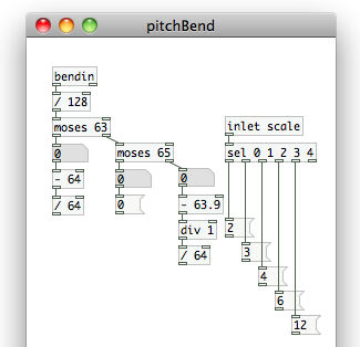 Create a new trigger atom, [t b f], and feed each of those 5 message atoms to its inlet. Create a [*] atom, connecting the float outlet of [t b f] to its cold inlet, and the “bang” outlet to its hot. Connect the outlets of each of the [moses] paths to the hot inlet of [*] as well.
 Let’s make sure we always load up the patch with the “2” message atom (2 semitones of pitch bend) selected. Create an object atom and type in “loadbang”. [loadbang] outputs a bang as soon as PD opens the patch. Connect that to the inlet of the [2] message atom. Now we can be sure there will always be a value feeding [*]; that’s our “fail-safe” value. Create an “outlet” atom, and connect that to [*]. We’re almost done with implementing pitch bend.
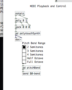
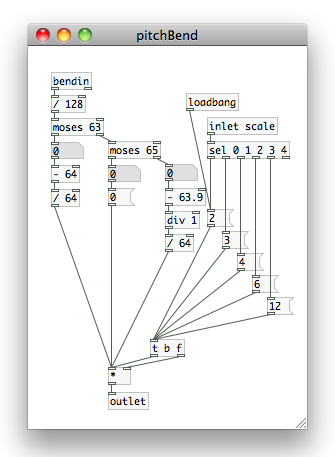 Close your [pd pitchBend] sub-patch, and examine that atom on your parent file. It should have an inlet and an outlet. To the outlet, create and connect [send $0-bend]. This will send our pitch bend value into the [pd polytouchSynth] sub-patch, which will in turn feed into all of our individual voice [sampleOscillators]. All we need to do now is give the user a simple way to select what range of pitch bend to use. Go to the “Put” menu, and select “Vradio” (or use shift+cmd+d). In its “properties menu (still a right-click on the atom to access) change the “number” field to “5”. Now connect the radio selector to the inlet of [pd pitchBend]. From top to bottom, the values the radio selector will output are 0, 1, 2, 3, and 4…just like what we used in our [select atom]. Use “comments” (cmd+5) to place “2 Semitones”, “3 Semitones”, “4 Semitones”, “Half Octave”, and “Full Octave” next to the appropriate boxes. You have fully implemented pitch bend. Go ahead and play around with it for a minute or two if you like.
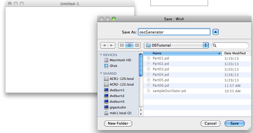
 Our next task is to implement frequency modulation. We’re also going to implement multiple wave shapes. To do this, we’ll eventually need to jump back into our [pd polytouchSynth] sub-patch. Before we do that, however, we’re going to create another abstraction patch. Create a new file, save it to the same directory as your synthesizer and “sampleOscillator” patches, and call it “oscGenerator”.
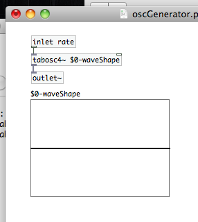
 We’re going to use this patch to define the wave shape of modulation applied to our signal. Let’s create two inlets, one labeled “rate” and one labeled “selector”. Create a new array using the “Put” menu, with a size of “67”, and call it “$0-waveShape”. By adding the “$0-” to the array name, we’ll be able to use this abstraction multiple times without creating conflicts between instantiations. Now create [tabosc4~ $0-waveShape] to play back that array, connect it to [inlet rate], then create an [outlet~] atom to send the resulting signal out of the abstraction patch.
 Now we’ll setup a system to define the shape of the array. Create a [select 0 1 2 3 4] atom and connect that to the output of [inlet selector]. We’re going to use a message command to create a waveform by providing the ratio of harmonics for each type. The base content of the message atom is going to be [sinesum 64]. The [sinesum] message atom fills an array of ‘n’ indexes (in our case 64). With the sum of a fundamental sine wave and its harmonic series. You may recognize that we have a bit of a mismatch between the array size (67, to work properly with [tabosc4~]) and the number of indexes in [sinesum]. Don’t worry, it will work just fine. We’re going to need 5 [sinesum 64] message atoms in total:
- We’ll work with at least 8 harmonic values (that’s including the fundamental) for each waveform, excluding the Sine wave…
- Sine Wave: pure fundamental frequency only: [sinesum 64 1]
- Rising Saw: the negative inverse of all harmonics (-1, -1/2, -1/3, etc.); we’ll halve the harmonics to avoid clipping, which basically means that we’re starting at the first harmonic (instead of the fundamental)…making our series 1/2, 1/4, 1/8, etc.: [sinesum 64 -0.5, -0.25, -0.167, -0.125, -0.062, -0.0331, -0.015, -0.0071]
- Falling Saw: the inverse of all harmonics, again halving the fundamental: [sinesum 64 0.5 0.25 0.167 0.125 0.062 0.0331 0.015 0.007]
- Square Wave: the inverse of odd number harmonics…1, 0, 1/3, o, 1/5, 0, 1/7, etc.: [sinesum 64 1 0 0.333 0 0.2 0 0.143 0 0.111 0 0.0909]
- Triangle Wave: the inverse of {odd number harmonics squared}, and every other odd harmonic needs to be a negative number, but starting with the “3rd” though (i.e 1, 0, 1/(3 squared), 0, -1/(5 squared), 0, 1/(7 squared), 0, -1/(9 squared), etc.)…t’s a little wacky, I know; we’re going to avoid clipping here by halving those numbers as well: [sinesum 64 0.5 0 -0.0556 0 0.02 0 -0.0102 0 0.00615]
Connect each of the outlets (from left to right) to the [sinesum] message atoms in the order I just gave you. Create the send object [s $0-waveShape], and connect each of those [sinesum messages to its inlet. This will send that data to the selected data to the array, allowing PD to calculate the wave form that should fill it. Finally, we want to create an initial selection upon load. Create a [loadbang] object atom, and connect it to the inlet of [sinesum 64 1], and the patch will load automatically load a sine wave into the “$0-waveShape” array when loaded.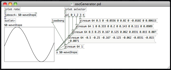 Save this patch, and feel free to close it after you have. Next, open up the [pd polytouchSynth] sub-patch, then open the [sampleOscillator] patch from within it. We need to add two atoms to this abstraction patch as part of our implementation of frequency modulation. Remember that our modulation output (the “oscGenerator” abstraction patch we just built) outputs an audio signal. This means that to modulate the frequency of playback, we need to insert this effect before the [tabosc4~ sample] atom, and after our [motf~] atom. Our modulating waveform is going to be swinging from negative to positive values and back. That means we can use simply use a [+~] atom (remember that we need a tilde because we’re dealing with an audio signal). Create that atom, then create the inlet atom [inlet~ fmMod] (again…audio signal)…keeping it to the right of the [inlet bend] atom…and connect it to the cold inlet of [+~]. Disconnect [mtof~] from [tabosc4~ sample] and insert the [+~] between them. Connect [mtof~] to [+~], and [+~] to [tabosc4~ sample]. Save the patch, and all of your [sampleOscillator] instantiations will be updated with the changes. They are now configured to apply frequency modulation to your signal.
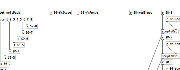
 Obviously, we’ve got a bit more left to do on FM implementation. Close the [sampleOscillator] abstraction patch, and move back up into the [pd polytouchSynth] patch. Notice that the [sampleOscillator] atoms now have a third inlet. We’re going to need three control parameters for frequency modulation here. We’ll establish those controls in the parent patch soon, but let’s prepare for them by creating [receive] atoms for each one: “$0-modShape”, “$0-fmRange”, and “$0-fmState” (is FM turned on or off?). After you’ve created those, line them up from right to left, leaving space between [r $0-modShape] and [r $0-fmRange] (we’ll need that space in the future).
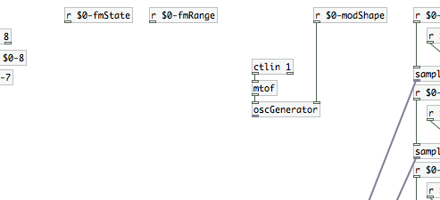
 Before we go further, we’re going to need to bring in the data from our mod wheel. Create the object atom [ctlin], three number atoms, and connect the number atoms to the outlets of [ctlin]. If you’ve got a MIDI controller with lots of different knobs, sliders, wheels, or what have you…then [ctlin] is going to be one of you best friends! Move your mod wheel and check out what happens in the number atoms. Outlet 1 outputs the controller’s value, the second outputs the controller’s ID, and the third outputs the channel. This atom is very similar to [notein] but it keeps track of additional MIDI control points on your controller. We only want to look at the mod wheel in our current application, but you can use this atom to determine the control ID and output behavior to map other controls for your synth (maybe FM rate, for example) to points on your MIDI controller if you want. Since the mod wheel’s ID number is assigned “1” (at least on my controller it is, you should check to confirm its the same for yours), I’m going to edit [ctlin] to be [ctlin 1]. That will tell this atom to look at controller ID 1 only. I will feed the left outlet (the controller value) to an [mtof] (note that I’m staying in data form here…no tilde), which I will then feed to the left inlet of a new atom, [oscGenerator] (our second abstraction patch). So, the MIDI value from my mod wheel will be converted to a frequency, which will feed our [oscGenerator]. We’ll also want to connect our [r $0-modShape] to the cold inlet of [oscGenerator].
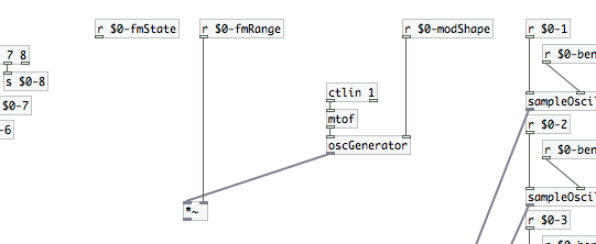
 Now that we’ve brought in [oscGenerator], we need to apply a frequency “range” to it. Create a [*~] and connect its cold inlet to [r $0-fmRange]. Then connect the outlet of [oscGenerator] to its hot inlet. That will complete our frequency modulation signal.
 We simply need to apply the FM signal to the signal being generated in [sampleOscillator]…that is, if the user has turned actually turned on FM. It’s time to introduce a new object atom, [spigot]. [spigot] is another of those wonderful atoms that can be applied to both data streams and signals. In its data form, [spigot], it only allows data to flow from its hot inlet to its outlet if it is receiving a non-zero number at its cold inlet. In its signal form, [spigot~], it has two outlets. When it receives a zero at its cold inlet, the signal passes out of its left outlet. If it receives a non-zero number, it passes the signal to its right outlet. This means we can use [spigot~] to turn a signal on and off, simply by what we connect to which outlet.
We’re going to need two [spigot~] atoms. Connect the [r $0-fmState] to the cold inlet of both atoms. On one atom, connect the outlet of [*~] from beneath the [r $0-fmRange]. The other [spigot~] atom should not affect our frequency at all, we want it to add nothing. We should still feed it a signal to ensure that though. We can use the object atom [sig~], with an argument of “0”, to do that. [sig~] converts numbers to audio signals, and adding an audio signal of 0 to the frequency signal that feeds [tabosc~4 sample] means we won’t actually generate frequency modulation. Create [sig~ 0] and connect it to the inlet of your other [spigot~].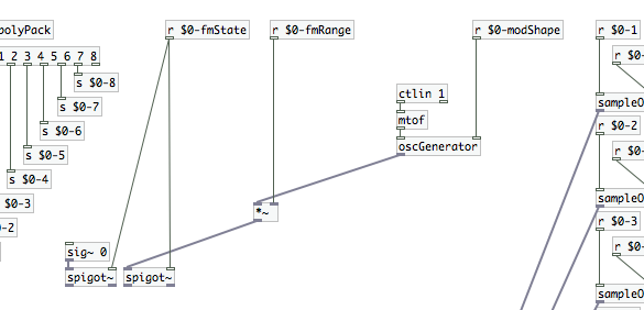 Create two [throw~ fmMod] atoms. Connect one to each of your [spigot~] atoms. For the [sig~ 0] -> [spigot~] chain, it should be connected to the left outlet…this will feed [sampleOscillator] when FM is set to “off.” The [oscGenerator] -> [*~] -> [spigot~] chain should output from [spigot~]’s right outlet only…this will be the chain that feeds [sampleOscillator] when FM is activated. Create another atom, [catch~ fmMod], and connect its outlet to the third inlet of each of your [sampleOscillator] instantiations. The [throw~] / [catch~] pair is the signal equivalent of [send] / [receive] (which only carries data). Like the [send] / [receive] pair, its a handy way to make your patches a little less cluttered…and multiple [throws~] can feed one [catch~].
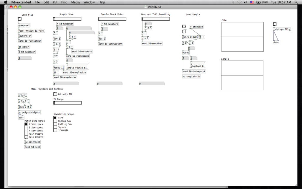
 We’re almost done with frequency modulation, and nearly done for today as well. Close the [pd polytouchSynth] sub-patch. The rest of our tasks will take place out in the parent patch. We need a [toggle], a horizontal slider, and Vradio…create each of those and make the following adjustments in their respective “properties” windows:
- Set the [toggle]’s “send-symbol” to “$0-fmState”
- Set the horizontal slider’s “send-symbol” to “$0-fmRange” (feel free to also change the “left” and “right” values if you like)
- Set the Vradio’s “send-symbol” to “$0-modShape” and its size to “5”.
You may want to use “comments” to label the toggle as “Activate FM”, the horizontal slider as “FM Range”, and the Vradio as Modulation Shape (with the boxes labeled, from top to bottom, as Sine, Rising Saw, Falling Saw, Square and Triangle). Your patch should look like the image at the head of the article.
With that you’ve finished implementation of the the different ways we’re going to affect pitch. Next time, we’re going to get into amplitude modulation and ADSR envelopes!
Pitch bend MIDI messages are made up of a Least Significant Byte and Most Significant Byte for a range of 0 – 16383 ([128 x 128] – 1). This was implemented to ensure smooth sweeps even over large pitch bend ranges. For example, using only one data byte (0 – 127, where 64 = no bend) to bend a note up or down one octave could result in noticeable jumps in pitch from one value to the next.
Most likely the Axiom controller is displaying the Most Significant Byte but sending the full message. Some controllers display both bytes, like the Akai MPK series.
Nice work on the tutorial, really enjoying the exercise!
Thanks for the excellent info, Matthew!
HI spigot~ is not available in my version of pd i used vanilla and extended and both gives me cant create spigot~ any suggestions? thanks!!
I figured it out lol
well a solution I did was the following:
I created a new abstraction: i gave it 2 inlets one inlet~ and other inlet for data
data inlet feeds 2 select objects with argument 1 in one and 2 in the other
since select sends bangs each select outlet(left outlet of each send) feeds a message object one is message 1 , message 2
so if toggle sends 1 select 1 will send a bang to message 1
if toggle sends 0 select 0 will bang the message 0
then i feed both messages to an inlet of a sig~so any gets converted to a signal (we need that to multiply signal to signal) finally
that signal gets multiplied with a *~ which left inlet comes straight from the inlet~ i made and the right inlet is getting the converted signal from sig~ ,either a 1 or 0 turning signal on or off this goes to an outlet~
in the polytouch patch i just forgot about the spigots and connected the multiplier output from range * oscGenerator to the left inlet the signal one and the right gets signal from the r $-fmState aka toggle
thats it it works hope it helps!!