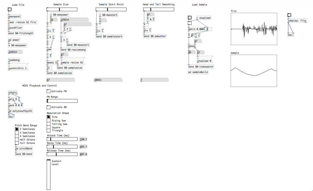
 Despite all of this, I’m still relatively new at Pure Data and the Max language. To those who chime in with corrections or clarifications in the comments, you are most appreciated! If you’re new to PD, make sure you check the comments section for clarifying info provided by generous souls.
Today is “amplitude” day in our wavetable synthesizer series. We’re going to be implementing amplitude modulation, as well as a method to control the ADSR envelope of our individual voices. Do I need to say this next part again? Well, I will just in case. This is part 7 in this series of tutorials. Reading parts 1 through 6 before tackling today’s tasks is encouraged. As with the last two tutorials, make sure you connect your MIDI device and configure it in PD before opening your patch. MIDI input and control won’t work otherwise.
Last time, we implemented frequency modulation mapped to the mod wheel. We’re going to start off today by finishing mod wheel implementations and give the user the choice of controlling amplitude modulation. This particular model will have both FM and AM mapped to the mod wheel. The user will have the choice of having one or the other, both simultaneously, or neither active. In the last article, I showed you how to identify a MIDI controller ID using the [ctlin] atom. Feel free to map AM to another control knob/wheel/whatever on your controller; though you’ll have to figure that one out on your own. ;) [Don’t worry, you should be able to figure it out between the FM code we built last time, and the AM code we’re about to build.]
AM will be significantly less time intensive to build, as we already did most of the heavy lifting last time. Nearly all of the work is going to be done in the [pd polytouchSynth] sub-patch. So open that up.
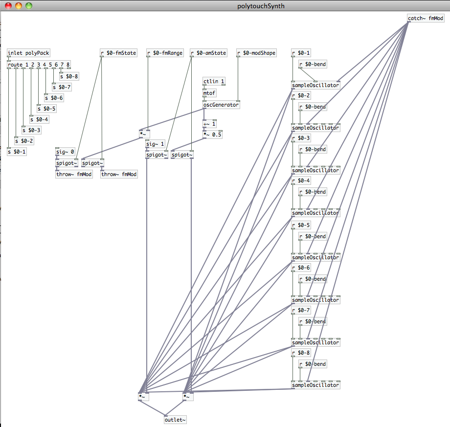
The first thing we’re going to create is a [receive] atom for the variable “$0-amState”. Place that atom in the space we left between [r $0-fmRange] and [r $0-modShape]. We’re also going to need two [spigot~] atoms to manage the “on/off” state of AM, just as we did FM. Connect [r $0-amState] to the cold inlets of those new [spigot~] atoms.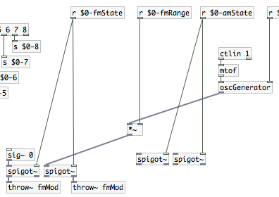 Disconnect each instantiation of [sampleOscillator] from [outlet~]. We’re going to be inserting a pair of atoms to work with the signals that will come down through the new [spigot~] pair, which we need to affect the signals out of the [sampleOscillator] atoms before the reach the sub-patch outlet. We’re going to be using [*~] to scale the output signals’ amplitude. First, we need the signals though. On the left [spigot~] connect a [sig~ 1] to the inlet. This will let us multiply the playback signals without causing a change (1*n=n, after all). Create a [+~ 1] atom and connect it to the outlet of [oscGenerator]. Then create a [*~ 0.5] atom and connect that to the [+~ 1] atom. This will constrain our modulating waveform to stay between 0 and 1 (“-1 to 1” becomes “0 to 2” thanks to the “+1”, then “0 to 1” thanks to the “*0.5”). That will prevent our amplitude modulation from affecting the phase of our signals. Connect that chain to the inlet of the right [spigot~]. If you haven’t already, go ahead and create two [*~] atoms. Connect the right outlet of the right hand [spigot~] ([+~ 1] -> [*~ 0.5] path) to the cold inlet of one [*~]. Connect the left outlet of the left [spigot~] ([sig~ 1] path) to the cold inlet of the other [*~]. Now connect the outlet of each [sampleOscillator] instantiation to the hot inlet of both [*~] atoms. Connect the outlets of the two [*~] to the [outlet~] atom. Your sub-patch should now look something like this.
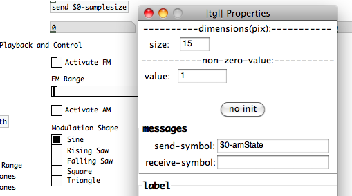
 You can close the sub-patch, as we now only have one more step to finish AM implementation; and we’re going to do that in the parent patch. Create a new [toggle], and open its “properties” menu. Set its “send-symbol” field to “$0-amState”. You may want to identify the [toggle] with a “comment” (cmd+5), but we’re now done with amplitude modulation implementation. It will use whatever wave shape you select in the parent patch. AM and FM share wave shape from the generator, which is controlled by the mod wheel. Meaning they share modulation rate/frequency as well. The individual [toggle] atoms for each let turn one or the other on, or both simultaneously…which can create some pretty wacky sounds. [note: We haven’t implemented a range control on the amplitude modulation. These articles are already pretty hefty. So, it could be a good implementation challenge for yourself if it’s something you want. ;)]
 Next up is ADSR envelopes. If you’re working with something that’s monophonic, or you’re creating an offline process, you can create linear fade envelopes very easily using the [vline~] object atom. Unfortunately, that won’t work for us here, as we’ve built a polyphonic synth that is controlled in real-time using MIDI. I mention [vline~] here only because it’s a tool that you might find useful if you start experimenting on your own. To have Attack, Decay, Sustain, and Release values that will affect each voice individually, we’re going to have to jump back down into our “sampleOscillator” abstraction patch again. You can open it up using the “File” menu, or by clicking on it in your [pd polytouchSynth] sub-patch. Take your pick.
We are easily going to double the amount of code that we have in our abstraction patch. So be prepared for some tricky routing. First, let’s consider how the how ADSR will function on our signal. The “Attack” will define how long it takes for our note to come to full volume. The “Decay” defines the time between the end of the “Attack” and the when the note reaches its “Sustain” level. The “Sustain” is simply at what volume the note will be held at from the end of the “Decay” section until it begins to “Release”. And we want the “Release” time to override MIDI “note-off”. That way it will take however much time we desire to fade to 0 amplitude, instead of simply ending once we release the key. So, our implementation will follow this pattern:
- From the time the key is pressed, it will take “x” seconds to come to full amplitude (a value of “1” in our oscillator)
- Once the volume reaches full amplitude (“1”) it will take “y” seconds to fade down to the “Sustain” level
- The “Sustain” level should use the same range as our oscillator does for amplitude (from “0” to “1”)
- The “Release” should be triggered by a MIDI note-off event and take “z” seconds to fade to “0”
We can use [moses] to bypass the velocity when a MIDI note off is received. Basically, we trigger the release fade when a “0” velocity is received, but continue to apply the original velocity value to that fade. Considering this behavior, it makes the most sense to implement this process between the oscillator, [tabosc4~ sample], and the application of MIDI velocity. We also need to apply the MIDI velocity value during the “Attack”, “Decay” and “Sustain”. So we should probably have those in between the two as well. The flow of code would be:
- Determine whether or not the velocity is a zero value. If it is, then apply the “Release” fade. If not…
- Apply “Attack” fade
- When the “Attack” fade ends, trigger the “Decay” fade
- When the “Decay” fade ends, hold at volume value “n” (range of 0 to 1)
- Apply MIDI velocity value to to all stages prior to outlet
Enough analysis let’s start building!
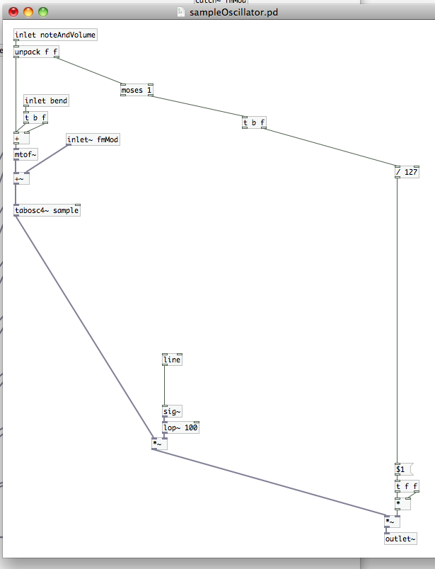
Disconnect [unpack f f] and [/ 127]. We’re going to start out with two atoms, [moses 1] and [t b f]. [moses 1] will let our abstraction patch determine if it needs to trigger the “Release” state or the “Attack” state. So, let’s connect that to the right outlet of [unpack f f]. If the velocity value is a one or greater then we need to pass that along to our velocity/volume path on the far right and trigger the “Attack”. [t b f] lets us do that, so we’ll connect its input to the right outlet of [moses 1]…and then we’ll connect the right outlet of [t b f] (the “f” or “float” outlet, because that’s how we’ve defined it) to [/ 127]. An interesting point about PD while we’re here. It processes all of the entire path of an outlet before processing the next outlet, and it always processes from right to left. That means our {MIDI velocity value to volume scale} calculation happens before it does anything else in the patch (other than unpacking the note and velocity values that is). That volume value is now sitting at the cold inlet of [*~], just waiting for a signal at the hot inlet to trigger the calculation. This order of operations is useful to know, as we’ll be taking advantage of it as we move forward today.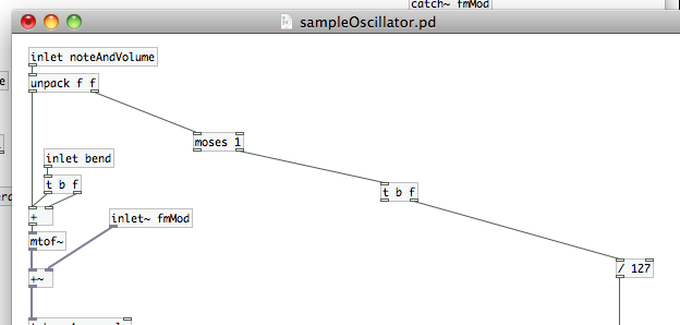 Let’s talk about how we’re going to work these fades now. We’re going to replace the current connection between [tabosc4~ sample] and [*~] at the end of the velocity chain on the far right. Go ahead and break that connection so we can make space for the new object atoms we’ll be placing. Do you remember the [vline~] object I talked about? Well, there’s another object that similar called [line]. In some ways it’s less robust than [vline~] (which can execute a full envelope), it can only create a single ramp. It can, however, work its magic on either data streams or signals. We like the fact that it can work on data streams, because that’s what we need here. Create the [line] object atom. Notice that it has two inlets and one outlet. The cold inlet is for duration…how long the ramp will take. The hot inlet is for target value…which direction the ramp is going, and where it will stop. The outlet spits out the continuously changing values until it hits the target. This is how we’re going to work our magic. I’ve noticed that [line], when applied directly to an audio signal, can create clicks as the ramp happens. To fix that, we’re going to insert a [sig~] atom right after it. Create it and connect it to the outlet of [line]. [sig~] will convert the output of [line] to an audio signal. This will provide us with a slightly smoother fade. Finally, to really ensure that the fade is completely smooth, we’re going to add a [lop~ 100] atom. [I’m stealing this trick from Andy Farnell…if you want to get really deep into PD and procedural audio, check out his book Designing Sound sometime.] This is a low-pass filter with a center frequency of 100; but, in this application, it actually affects the rate of change that [sig~] feeds to [*~]…eliminating the remaining artifacts. [note: [vline~] is better at creating these kinds of audio fades than [line] and does not need [sig~] or [lop~] after it to smooth it out.] Create a [*~] atom and connect [sig~] to its cold inlet. Connect the hot inlet of [*~] to [tabosc4~ sample], and the outlet to the inlet of our other [*~] at the end of the velocity chain on the far right.
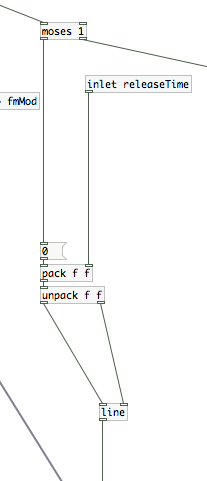
 Let’s jump back up to the [moses 1] that we placed earlier. We’re going to start the fades by building our “Release”…as it’s the simplest of the three. Create a message atom with the value “0” and connect it to the outlet of [moses 1]. We’re using this as both a fail-safe and a “bang”. We’re going to need an [inlet] to accept our user defined “releaseTime”. These are our two values for [line], but we need to control when they are passed to [line] and in what order. Using a [trigger] atom here would get a bit complicated. Instead we’re going to use a [pack] / [unpack] pair. We’ll be passing two “floats”, so we’ll need [pack f f] and [unpack f f]. Connect [inlet releaseTime] to the cold inlet of [pack f f]. That value will be stored in the right “f”, waiting for a “bang” at the hot inlet. Connect the [0] to the hot inlet, which will trigger [pack f f] to build and output the list…only when there’s a MIDI velocity value of “0” (or note-off). Make the connection to pass this list to [unpack f f]; which passes the release time value out of its right outlet first (remember when I mentioned processes are completed from right to left?), and then the target value (“0”) out of its left outlet. Do you see where this is going yet? Connect the right outlet of [unpack f f] to the cold inlet of [line], and the left outlet to the hot inlet. We’ve just built a structure that ensures [line] receives the data it needs…in the correct order…to create the release fade.
 Our “Attack” code is virtually identical. Copy and paste the “Release” code you just built (only those items in between [moses 1] and [line]). Shift the pasted code a little farther over to the right to connect to the next atom up top, [t b f]. Change the message atom from “0” to “1”, and change the [inlet] identifier from “releaseTime” to “attackTime”. Connect the “bang” outlet of [t b f] to the inlet of [1], and connect the outlets of the second [unpack f f] to [line] just as we did under [moses 1].
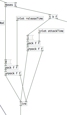 Next comes the “Decay” code, and this is a bit more complicated than we’ve had to get with the previous two. First, we need a Boolean argument…[== 1]. [==] will check the incoming value to see if it matches the argument or cold inlet (in our case, the argument “1”). We’re using it to check and see if the “attack” fade has completed. When the comparison is “true” [== 1] will output a “1” value; it will output a “0” whenever it is false. Connect this atom to the outlet of [line], and then create a the send atom [s $0-decayBang]. This is a simple way for us to start our “Decay” fade.
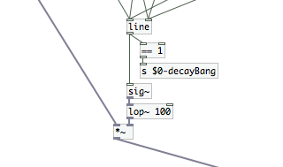 We’re outputting a “1” and a “0”. Seems like a good way to control a [toggle] doesn’t it? ;) First create two final inlets, “sustainLevel” and “decayTime”. Put those up closer to the top, with “decayTime” to the right of “sustainLevel” (which is to the right of “attackTime”, which is to the right of “releaseTime”, etc.). Underneath those, create a receive atom for “$0-decayBang” and a [toggle]. Connect the outlet of [r $0-decayBang] to the [toggle], and connect that to a new [trigger] atom with the argument “b f b f”.
 Remember that [trigger] atoms can be set up to control any number of actions. We’re using this one to output, from right to left, the [toggle] value (either a 1 or a zero), a “bang”, the value once again, and another “bang”. We’re going to combine a pair of [float] atoms with a pair of [spigot] (note the lack of tilde this time…data!) to feed the next [pack] / [unpack] pair. Here’s how we do this:
- Place a pair of [f] atoms directly underneath [t b f b f]. Connect [inlet decayTime] to the cold inlet of the right hand [f] and connect the [inlet sustainLevel] to the cold inlet of the left hand [f]. These [f] atoms will hold the values from the inlets until we need them. Then, we’ll trigger them with a ‘bang”.
- Place a pair of [spigot] atoms underneath the the [f] atoms. Connect the right [f] atom to the hot inlet of the right [spigot], and the left [f] to the hot inlet of the left [spigot].
- Now we’ll make connections from the [t b f b f]. From RIGHT TO LEFT, connect the first float to the cold inlet of the right [spigot]. Connect the first “bang” to the hot inlet of the right [f]. Connect the second [f] to the cold inlet of the left [spigot]. Connect the second “bang” to the hot inlet of the left [f].
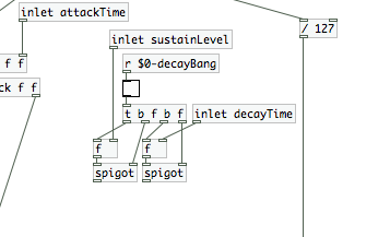 Now we’ll create another set of [pack f f] feeding into [unpack f f]. Connect the right [spigot] to the cold inlet of [pack f f], and connect the left [spigot] to the hot inlet. Connect [pack f f] to [unpack f f] if you haven’t already, then feed [unpack f f] to [line] as we have the last two times.
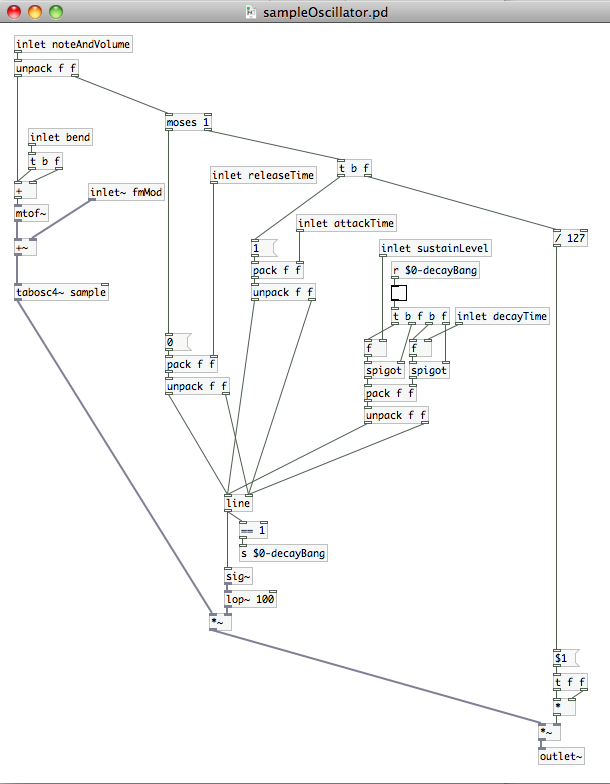 We’re done with our edits to the [sampleOscillator] abstraction patch. Make sure to save it before closing it. [Also, remember what I’ve said in the past about sometimes needing to re-open the parent patch when you’ve made changes to an abstraction patch that appears multiple times.] Before we move on, though, I want to point out a behavioral oddity in this new version of “sampleOscillator”. When you finally start using this, you may notice the PD console window throw up a “stack overflow” error every time you press a key on your MIDI controller. The cause of that is somewhere in the [line] -> [== 1] -> [send]/[receive] -> [toggle] chain. We’re using [== 1] to identify when the “Attack” ramp is complete. I believe that, on my computer at least, the CPU is able to complete multiple cycles of this prior to the “Decay” ramp dropping the value of [line] below “1”. Once it catches up, things are fine. I haven’t had time to come up with an alternative method that prevents this error, but it is in no way critical. Basically, like the “error: moses: no method for bang” message we receive when setting the sample parameters, this is an error we can ignore.
We are done with major coding tasks of our envelope generator. All that’s left is to generate a user interface to define the envelope, and create a path for the data to get into the [sampleOscillator] instantiations. Be sure that your inlets look similar to how they appear in the picture above. My next instructions will depend on their left/right orientation…because that affects which inlets we will connect to. We can close the “sampleOscillator” abstraction path, and move back into the [pd polytouchSynth] sub-patch. Take a look at your [sampleOscillator] instantiations. They should now have an additional four inlets. The order of inlets, across the whole atom…from left to right, is now: MIDI note list, pitch bend, fmMod signal (the one gray inlet), release time, attack time, sustain level, and decay time. Create four [receive] atoms with the variables: “$0-release”, “$0-attack”, “$0-sustain”, and “$0-decay”. This is where things will get a little crowded. You need to connect the outlets of these receive atoms to the inlets of every [sampleOscillator] in the manner shown below.
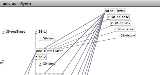 Alternatively, you could create [receive] atoms for each of the individual instantiations…much as we did with [r $0-bend]. That actually requires more keystrokes, in addition to the “click-drag-release” for every connection. I’m a lazy man sometimes…here’s what my sub-patch looks like.
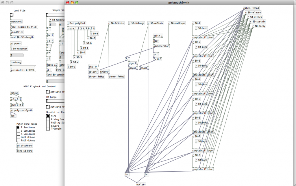 Now you see why I chose for us to build this as a sub-patch. There’s a lot of real-estate that’s been eaten up by this code. It’s nothing that we need to interact with on a regular basis, so there’s no reason to clutter up the parent patch with all of it. We’re also done making edits to this patch. If you’ve done everything correctly, there will be no need to open this or the “sampleOscillator” abstraction patch again.
All we have left to do is create our user interface for the envelope generator. In the parent patch, create three horizontal sliders, three number atoms, and one vertical slider. You are going to set each of the horizontal sliders’ “send-symbol”s to use one of the variables we just created in the [pd polytouchSynth] sub-patch: “$0-attack”, “$0-decay” and “$0-release”. While you have each property window open, you may want to change the value of the “right” number under the “output-range” section. I’ve set each of mine to 3000, but you can do more or less as you like. This will determine the maximum duration of each ramp in milliseconds…with my example totaling 3 seconds. You’ll probably want to label each slider with a “comment” so you can remember which one does what. The number atoms are there so that the user can see how many milliseconds they’ve actually set it to. Simply place one next to each slider, and change the “receive-symbol” field to match the “send-symbol” of the slider it is next to.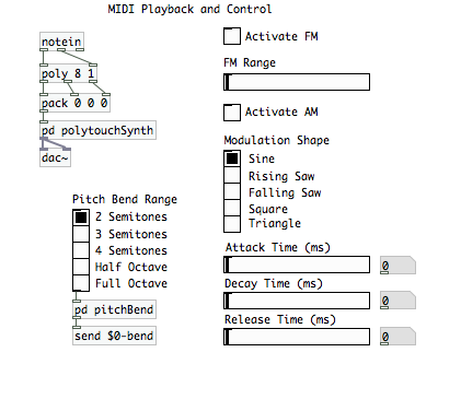 Open the vertical slider’s properties menu and look at the “output-range” section. This is what we will use to set the “Sustain” level. Change the “bottom” value to 0.01 (or it can be higher if you like) and the “top value to “0.9999”. We don’t want the sustain level to be “0”…that would be pointless. Neither do we want it to be “1”, as that might prevent our note from shutting off. Remember that we’re comparing the output of [line] to “1” in our “sampleOscillator” patch. We could end up in an infinite loop there, constantly triggering the “Decay” ramp. Setting the max “Sustain” level to “0.9999” gives us a transparent way to prevent that, and we won’t be able to hear a .01% level change from a note’s maximum volume. While we still have the properties window open and are looking at the “output-range” section, look for a button labeled “lin”. That stands for “linear,” and it defines the output vs. position behavior of the slider. Click that button once, and it should change to “log”…for logarithmic. We also want to set this slider up to start at its max volume. It’s just more user friendly that way. In the “receive-symbol” field, type “sustainInit”. We can close the properties window now; so click “OK”. We can use a [loadbang] atom to trigger a PD command message to set the value of “sustainInit.” Remember how we did that a few articles ago? Create a message atom and type the following: “;”, then enter/return, followed by “sustainInit 0.9999”. Connect that atom to your [loadbang] and place it where you have space that makes sense. I put mine right underneath the “Load File” section. [You can see it to the left of the “|vsl| Properties” window in the image below.
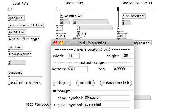 Our vertical slider is now a simple volume fader. We have a great visual representation of where the “Sustain” level is, so we don’t really need a number atom like we did with the sliders. Label the slider, and with that we’re done! We can set the duration of the “Attack” ramp, the duration of the “Decay” ramp and to what level it will drop (the “Sustain” level), and the duration of the fade out (“Release”) once a note-off message is received. We’ve built a user defined envelope with an interface of just four sliders! Just one last reminder that you can make fine adjustments on the sliders by holding the shift button before you click and drag. It’s useful for getting more precise changes…especially over ranges as large as I’ve set up on the ADR sliders.
Have fun with your patch until next time…when we’ll be adding in a filter section to our synthesizer.
Stack overflow errors are the result of Pd running out of memory when asked to run a recursive operation. Generally this is a bad thing, but it doesn’t seem to be causing a crash in this case. FWIW, I’m only seeing the error when holding a key down longer than the attack time.
I haven’t attempted to debug in depth, but eliminating the $0-decayBang [send]/[receive] pair and patching directly gets rid of the error for me. But if it ain’t broke…
Starting to sound really good, nice work!
Thanks for sharing this information. I’m starting with Pure Data and it was quite interesting and helpful to read your post :-)
Hi there!
I’ve built this synth up to the end of part 7.
Before I started part 7, my Midi-keyboard was able to control the sound but now that I’ve finished this part, it doesn’t play anything anymore…
My (toggle->[tabplay~ file]->[dac~]) path at the top right of my patch does still play the loaded sample when I click on it and I’ve put a number-atom under my notein (at the top of my MIDI playback and control) wich shows the MIDI-value of the keys I press so it’ coming through so far.
But when I select test Audio and MIDI in pd’s media-tab it shows me that [ctlin] is not receiving any data..
I can’t seem to find a solution by myself, could anyone please help me out?
Great tutorial by the way.
Really enjoing it,
Brian.