Compressors have become more than just gain control units, they can be just as important as EQs in shaping a sound and sometimes even more so. For the mathematically inclined, a compressor works with a transfer function, or in plain speak, it changes its input in a predictable way. The controls of a compressor help specify this transfer function. The most common controls include: threshold (specifies when the compressor kicks in, usually in decibels), ratio (the amount a signal is compressed once it crosses the threshold), attack (the time taken for the compressor to begin compressing once the signal crosses the threshold), release (the time taken for the signal to return to ‘normal’, i.e., for the compressor to stop having an effect) and make-up gain (a post compression gain). It is quite common for a compressor to have other controls like specifying an alternate side-chain signal, filtering of the side-chain signal, choice between RMS and peak detection or look ahead (where the signal is delayed and then compressed).
Building a compressor in Pure Data (or Max) can be fairly straightforward – depending on the functionality you are looking for. For the purpose of this post I will include the following controls:
- Threshold
- Ratio
- Attack and release (with a unified control to keep things simple)
- A choice between peak and RMS detection
- Make-up gain
- Lookahead
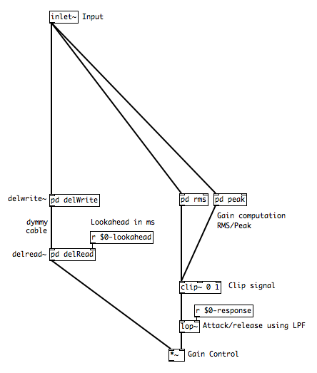
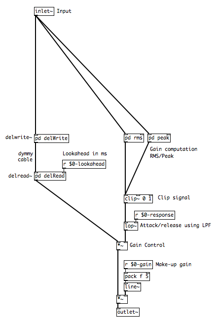
A typical compressor works by analysing the input signal and applying a reduction in gain to this same input signal based on the parameters specified (threshold, ratio, etc). A simplified schematic:
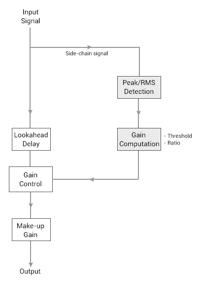 Most of the magic and sound trickery in a compresor is in the way it analyses the signal and computes the gain. There’s lots of information about this available on the web (including the excellent post by Herbert Goldberg that Shaun mentioned the other day). For this post, I have followed a fantastic paper on compressor design and implemented a portion of it into Pure Data Vanilla (I have mentioned the Max equivalent objects along the way and have included a comparison chart towards the end of this post). To also keep things simple I have unified the attack and release times, i.e., the attack and release times are the same. This is not entirely ideal as it decreases the flexibility and creative use of the compressor.
Signal Detection:
RMS:
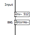
Calculating the RMS of the side-chain signal in both Pd and Max is fairly straightforward. In Pd it is calculated with the [env~] object and in Max with the [average~] object (check the help file in Max for the object as you will have to switch it to RMS mode).
The RMS of a signal is calculated by windowing the signal (followed by more maths) and the [env~] object allows the window size to be specified in samples, which I have set to 512. The [env~] object also follows a strange decibel convention (as with most dB related objects in Pd). 100dB equates to no gain (or a signal multiplied by 1, [*~ 1]), anything above 100 is a positive change in gain (103dB is [*~ 1.412]) and anything below hundred is a negative change (97dB is [*~ 0.707]).
The [*~] object in Pd (or Max) is commonly used like an amplifier – to scale signals. It can compute only linear numbers, not decibels. The [dbtorms~] object helps make the output of [env~] compatible with [*~] (it converts dB to linear amplitude).
Peak:
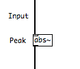
The peak of a signal is detected by taking the absolute of the input signal (check the above mentioned paper if you want more information). In Pd and Max this can be done using the [abs~] object.
Done!
Gain Computation:
Calculating the gain change for the compressor can be tricky. Fortunately it has been specified as a formula (worry not, the maths is not too hardcore) in the above mentioned paper:
If the level of the signal is below the threshold,
output = input
If the level of the signal is above the threshold,
output = threshold + (input - threshold)/ratio
This formula is for a hard knee compressor. A soft knee compressor is a little more complicated.
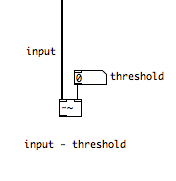
To implement this formula in Pd it would be best to break it down into smaller chunks (unless you want to get handy with the expr/expr~ objects). First:
input - threshold
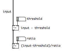
The output of that calculation is divided by ratio:
(input - threshold)/ratio
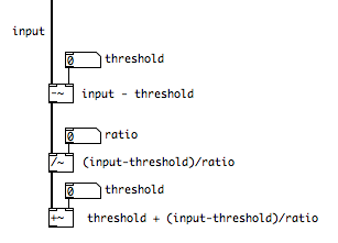
The output of that is added with the threshold:
threshold + (input - threshold)/ratio
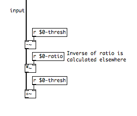
To make the patch tidier and easier to use, it would be best to use sends and receives with a $0 tag (this helps create local send and receives, just incase you have multiple instances of the patch running). The sends and receives will also make it easer to communicate with the rest of the patch and a GUI if required. Furthermore, division (/) calculations are more expensive than multiplication (*) so it would be better to replace the [/~] with a [*~] for the ratio calculation and calculate the inverse of the ratio (1/ratio) in the message domain instead of the signal domain elsewhere in the patch.
The last step of the gain computation process requires the output of the formula to be divided by the input. I’ve also added in the signal detection components and created a sub-patch for each detection type (the [+~ 0] doesn’t do anything other than keeping the patch neat).
The RMS gain computation sub-patch:
The Peak gain computation sub-patch:
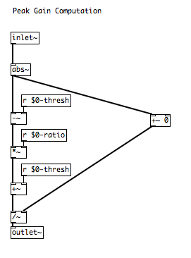 Done! When patching the controls of the compressor together I’ll add a control to switch between the two detection types.
Clip and Response:
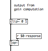
To stop the compressor from gaining the signal (positively) when the threshold is at 0 I’ve used the [clip~] object:
The next step is to add the attack/release control. Since it is a unified control (both the attack and release have the same time), I have used a low pass filter as a ramp generator. By converting time (in ms) to frequency (frequency = 1000/time), the lowpass filter can be used as an attack and release control. For ease of use and control I have also created a receive object to control the frequency of the filter.
Lookahead:
The lookahead feature in a compressor works by delaying the input signal before the gain control stage (not the signal being analysed, the image at the top of the post illustrates this).
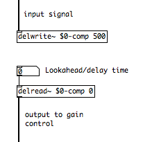
A delay in Pd can be created using [delwrite~] and [delread~] objects (in Max use [tapin~] and [tapout~]). Here’s what it looks like:
The [delwrite~] object requires a name followed by the maximum delay time in milliseconds and the [delread~] object required the name of the [delwrite~] object, while the delay time can be specified at its inlet.
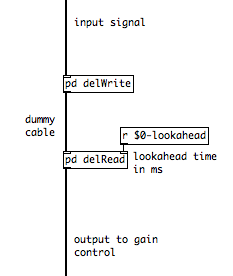
If the delay objects are patched like the way they are in the above image, Pd will be unable to delay a signal less than its block size (if this goes over your head just remember that Pd won’t be able to delay a signal less than 1.4ms in a typical setup). To overcome this problem the delay objects must be encapsulated into sub-patches that are connected by a dummy cable (for more information about this look up Pd help). I have also created a receive object to change the delay/lookahead time remotely.
Done!
Make-up Gain:
Here’s an overview of the patch so far:
Adding a make-up gain feature is as simple as using another [*~] after the gain control, although with the [line~] object to smoothen incoming control data (I’ve created a receive object named $0-gain):
RMS/Peak Switch:
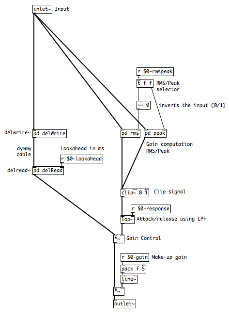
If the patch is run in its above state, both the Peak and RMS detection modules will work simultaneously. What is needed is a switch, that turns one module on and the other off.
If the [switch~] object is placed in a Pd subpatch, it can be used to toggle its DSP state. Sending a “1” toggles the DSP of that sub-patch (i.e., make the sub-patch work) and a “0” turns it off.
Here’s the Peak sub-patch with the [switch~] object and an inlet to control its state (the RMS sub-patch is similar):
The parent patch needs something that turns the switch~ of one subpatch on, while turning the other off. Here’s how I’ve implemented it:
The [== 0] inverts the input. If it receives a 0, it spits out a 1 and vice-versa. The above setup ensures that if [r $0-rmspeak] is sent a 0, the RMS module is activated and the peak module deactivated.
Control:
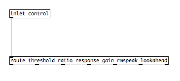
I’m not a fan of patches with tens of inlets. I’d rather use message boxes so I can keep patches organised and tidy while also being able to save settings with the patch. To control the compressor I’ve included a single inlet connected to a route object:
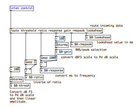
If the [route] object is sent messages “threshold -10” and “ratio 2”, it will spit out “-10” from the first inlet and “2” from the second inlet and so on. Each outlet is connected to their respective sends (that send the data to their respective receives). I have also also included other objects to standardise and translate the incoming data.
I wanted the compressor to be used like most other digital compressors out there – with the controls in the dBFS scale.
- Threshold: Threshold values need to be specified from a range of 0dB to -100dB. To make the values compatible, I first convert the values to the Pd dB scale (which I mentioned earlier) by adding 100 and then using the [dbtorms] object to convert the dB value to a linear amplitude value (the name of the [dbtorms] object is a bit misleading, it should be named [dbtolinear]).
- Ratio: The gain computation formula used the inverse of the ratio. The [swap] and [/] objects calculate the inverse of the ratio
- Response: Specified in milliseconds, the value is converted to frequency (for the low pass filter)
- Makeup gain: Similar to the threshold, dBFS values are converted to linear amplitude values
Done!
Here’s the final patch, with some additional features to initialise the compressor and send/receive values to a UI object (click to zoom):
Here’s the patch with a GUI abstraction:
Feel free to download the patches (below). Any thoughts, comments or suggestions are welcome!
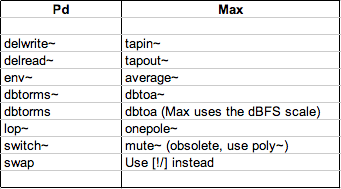
A comparison of Pd and Max objects (note: Max uses a dBFS scale unlike Pd and the [average~] object outputs linear amplitude values):
[wpdm_package id=’36942′]
EDIT: The aim was to get a compressor working in Pd Vanilla. With Pd Extended (and even Max) there are a lot more objects, like [slide~] and [rampsmooth~] that can make things a bit easier.





Fabulous article, I like the the interoperability of max and pd, just what I am after in my migration from one to the other.
On the other hand I thought: what about the relation between the delay and the length of the analysed frame?
Thanks Roberto.
Regarding delay times, block sizes and signal ordering, no better person that Miller Puckette to explain it: http://crca.ucsd.edu/~msp/techniques/latest/book-html/node120.html
Is there a book or blog that explains a compresser and its creative functionalities for those not mathematically inclined? Some of us have Dyscalculia. Theoretic explanations, are what really sings in my mind. For example, the book “Sound FX” by Case is a great balance of math and using language and analogies to explain. I’d love a book/paper really focused on compressors and their many creative uses from the perspectives of multiple producers.
Any pointing in the right direction would be amazing!
All the best!
The paper I linked to is great: http://www.eecs.qmul.ac.uk/~josh/documents/GiannoulisMassbergReiss-dynamicrangecompression-JAES2012.pdf
If you want more meat, check out the book DAFX – everything DSP related. http://www.amazon.co.uk/DAFX-Digital-Udo-ouml-lzer/dp/0470665998
Apologies, I misread your comment. For a non-mathematical explanation I suggest going through soundonsound.com : lots of articles over the years on compression.
great tutorial! I’d love to see more pd articles on here!
Nice post! It’s hard to find good examples of Pure Data.
Thanks Varun for this excellent article. This is just what I was looking for!
I am a little surprised that PD does not have such a basic thing in their help files.
I05 looks promising as it uses the FFT, but then uses distortion-inducing clip!
There is also “compressor” in pd-extended under “unauthorized”, but it is not documented, and seems to roll off the high frequencies during compression.
I am excited to try out your compressor circuit.
Thanks for this tutorial, and for releasing the code under a Creative Commons license!
“Feel free to download the patches (below). Any thoughts, comments or suggestions are welcome!”
WHERE ARE THEYEYYYYY!!?? Ive been looking everywhere “below!” and its just comments! Dang Im going to have to make them :P
It seems like the files were lost when our server was migrated last year. I do have them on a backup drive, but I won’t access to the drive for a few weeks. Sorry!
Thanks a lot for this!
Could you explain why you divide the output of the gain computer by the original signal amplitude right at the end of the gain computer? As I didn’t understand the reason for this however the patch doesn’t work with out it
Many thanks!
By dividing the signal we get the ratio of gain change. The compressor works by taking the amount by which the gain has changed and compressing the signal.
Thanks for your reply!
I think you may have misunderstood my question though. I am not referring to the ratio division but the very last division object in the gain computation section before leaving the gain computation sub patch. It looks like a division which divides the output of all the calculations by the original values of the signal. It says in the description ‘The last step of the gain computation process requires the output of the formula to be divided by the input.’ but it doesn’t explain why?
Hi! I am unable to download the patch. Is it still up? Could someone send it to me? I’d be super greatful :)
–> [email protected]
Thanks!
See Varun’s most recent comment (March 26th), just above. He’ll get it up as soon as he can, though it will likely take a while.
Oh, right! Thanks :)
Actually all I want to know is how the [pd delWrite] and [pd delRead] look like on the inside (because he must have added something in order to get the inlet slots on the outside…?
Using the [inlet~] and [outlet~] objects in the subpatch :)
Give me a heads up when download link is up. I tried building but must have done it wrong.
HI!
how the [pd delWrite, [pd delRead] and [pd dump] look like on the inside?
Has someone made this compressor?
Hey their, sorry were the download files available yet to download?
Sorry for the delay everyone. The file is back up for download.
Hi Varun,
thank you for this great explanation and patch – I’ve been using it in live performances!
I’d like to know how you’d go about making one such that attack and release are independently controlled – I’m not sure even where to start, and any help would be appreciated.